
PCB Design Tutorial for Industry Part Creation Part 2 Altium Develop
🛍️ Products Mentioned (1)
Try Altium Develop for your business today: https://www.altium.com/yt/kirschmackey @AltiumStories @AltiumAcademy #altiumstories Your PCB hardware design team having trouble standardizing PCB designs? Watch this video to build a part from scratch the right way that scales. Understand why hardware should be designed a certain way and why. The business impact.
About This Video
Frequently Asked Questions
🎬 More from TechEdKirsch
Hardware PCB design best practices for adding components (shown using Altium)
169 views

How Do Companies Create Hardware Products? Process Overview for Electrical Engineers
128 views
What is Altium Doing in 2026? Altium Develop and Agile The Best for Hardware Companies???
222 views
Altium Develop - Adding components to your workspace (for SMBs)
143 views
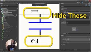
Altium Designer Tip - How to Make Pin Numbers Not Visible for Teams and Enterprise
48 views
Altium Designer Develop 2026 Part 1 - Installation and What is it?
481 views