
Inductance Isn't In The Wire Here's Where It Actually Is
🛍️ Products Mentioned (3)

Master Electrical Engineering: $297 EMC course - https://academy.hasofu.com/course/crash-course-emc-emi-signal-integrity $97 roadmap https://academy.hasofu.com/course/pro-hardware-pcb-designer-roadmap Design PCBs with Altium Designer → https://www.altium.com/yt/kirschmackey @AltiumStories #altiumstories You've seen the equation V = L(di/dt). But do you actually know what it means? In Lecture 1, we established why the electromagnetic field is the foundation of all electronics. In Lecture 2, we explored how electric fields interact with dielectrics (capacitance) and magnetic fields interact with conductors (inductance). Now we go deeper. This lecture is a case study in inductance—not as a component, but as a phenomenon. You'll see exactly how a changing magnetic field induces an electric field, how that electric field moves electrons, and how those moving electrons create their own opposing magnetic field. That opposition? That's inductance. That's Lenz's Law in action. We'll also cover why current lags voltage in inductive circuits (it's not magic—it's physics), and build up to transformers: how engineers figured out they could guide magnetic flux through ferromagnetic cores to step voltage up or down while conserving power. By the end, you'll understand why L = V/(di/dt) isn't just a formula to memorize—it's a ratio describing real field interactions in real materials. TIMESTAMPS: 0:00 - Welcome to Lesson 3 0:12 - Recap: Why we start with EM fields (Lesson 1) 0:18 - Recap: Field-matter interactions (Lesson 2) 0:43 - Today's focus: Foundation of inductance 1:19 - What affects inductance: trace length, loop area, cross-section 1:27 - Examples we'll cover: transformers, PCB traces, inductors 1:39 - Review: Cascading effect of magnetic fields in conductors 2:14 - Visualizing B field passing through copper 3:08 - Changing B field → induced E field 3:25 - Induced E field → electron movement → current 3:38 - B0 (original field) vs B1 (induced opposing field) 4:09 - EMF: Electromotive force explained 4:39 - Why electron flow isn't instantaneous 4:57 - Phase relationship: Why current lags voltage 5:16 - Preview of inductor behavior 5:31 - The equations behind the phenomenon 10:45 - Force equations and current behavior 17:30 - Practical inductance factors: geometry and materials 27:08 - Ferromagnetic materials and permeability (μ) 27:24 - Magnetic flux and how it flows through cores 29:01 - Engineering insight: Guiding flux to another coil 29:28 - Induced current on secondary windings 30:13 - Turns ratio and voltage transformation 30:43 - Power conservation: V₁ × I₁ = V₂ × I₂ 31:04 - Why transformers matter for power transmission 32:36 - The formal inductance equation: L = V/(di/dt) 33:14 - Summary and preview of Lesson 4 (electric field in dielectrics) About me: Former Intel senior-level hardware engineer (Silicon Valley HQ). Former adjunct professor teaching electronics foundations and PCB design. Background spans power systems, power electronics, embedded systems, FPGA, and high-speed PCB design. Watch the previous lectures: Lecture 1: https://youtu.be/alkhuPiYjkI Lecture 2: https://youtu.be/JPS05Wn-8v0
About This Video
Frequently Asked Questions
🎬 More from TechEdKirsch

Hardware PCB design best practices for adding components (shown using Altium)
169 views

How Do Companies Create Hardware Products? Process Overview for Electrical Engineers
128 views

What is Altium Doing in 2026? Altium Develop and Agile The Best for Hardware Companies???
222 views

Altium Develop - Adding components to your workspace (for SMBs)
143 views
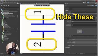
Altium Designer Tip - How to Make Pin Numbers Not Visible for Teams and Enterprise
48 views

Altium Designer Develop 2026 Part 1 - Installation and What is it?
481 views