
Is this your channel?
here
here
This is the exact Flipsky Dual FSESC 4.2 Smart ESC I’m looking at in the video, with the smart power button and aluminium case. If you’re planning a DIY build and want a cleaner, more integrated ESC package, this is the one I’m pointing you to from the description link.
Buy on Flipsky
You'll be taken to Flipsky to complete your purchase.
Pros
- +Smart power button setup for a cleaner build
- +Aluminium case for a more finished, protected package
- +Rated at 50A continuous (as advertised)
Cons
- -You still need to match it properly to your motors and battery for your build
- -Specs don’t replace good wiring, cooling, and sensible setup
What Lee Wright says
“2 smart now i want to pre-face this video by saying i do have quite extensive experience with a range of escs that have been out over the years starting with the humble fox box now i have a pair of these in my first ever diy board the duck and they've been going strong ever since i also have one more here which is unusual these days to actually find these things they're getting to be pretty rare they've all blown up or whatever ended up in landfill i guess also the zenith and before that the foxbox unity all the way up to the stormcore the spintend i've seen quite a lot of them um so i hope that i can do this video some good justice i also want to say that flip sky did send me two of these over full review for free and i'm gonna be giving one of them away so stick by for the end of the video and there'll be a question for you to answer so you can win one of these and i nearly worked myself in the eye that was ridiculous so look out in the video for a question you gotta answer put the answer in the comments and i will pick one of you guys randomly to win one of these dual 4”
“2 smart well it is one of a new generation of esc's that flip sky have developed they didn't always look like this one this is what the old generation of esc's look like from flip sky and to be honest they do have mixed reviews um it seems to be if you've got a good one it would last you absolutely forever but not everybody got a good one now this esc and all of the other ones in the same line of products seem to have had a bit of a redesign they don't only do this in a dual they also do a single and they also do a version six one as well which is a little bit more powerful but yeah i have the version four one and it is different i think this is a version for old one and this is the version for new one and it has had a significant redesign and there is a trick in this esc that i haven't seen on any other esc's before that doesn't mean it doesn't exist i've just never seen it and we'll be talking about that in a little bit but the esc itself is a 12s safe dual esc up to 50 amps per motor continuously and the the best thing about this so in my opinion one of the best things about this is the fact that it now has a smart switch so it has an e-switch built in it has the anti-spark circuit all built into this so you can turn the board on and off with a momentary switch which is pretty nice it's 336 dollars which may seem a little bit on the expensive side but if this is a good esc then it's worth investing a little bit more money in in a good esc and you might look at these specs i think well i could get a zenith and that would be 80 amps continuous for around about the same price but actually hopefully this has been under spec by flip sky and it can be ran a little bit harder than that and we will be trying to find that out later now as for the physical properties of this esc and please excuse the fact that i'm using a tape measure my calipers have seen some serious action recently i've just discovered they're out of battery looks like 121 wide 89 millimeters long and about 21 millimeters high so it's actually quite compact it's not compact to some others i'll put it against the zenith it's a little bit bigger tiny bit not much though and it's coming in at 285 grams but it doesn't have any connectors on it at the moment it has a hard aluminium body around the outside which is really nice and feels really premium and it has what you might think at first is a heatsink on the bottom but it's not actually a heatsink this esc doesn't really have an extra heatsink because the pcb on this esc is made out of aluminium the substrate is aluminium now normal pcbs are made of like a fibrous material doesn't matter what color they are green white red blue black they're made of like a fibrous material and that doesn't conduct heat very well so normally you put a heat sink on the power stage to transfer the heat out of the fets and into an external heatsink now this doesn't have an external heat sink as standard but with this large aluminium base plate or pcb base plate it's going to be interesting to see how this handles the thermals personally i think it's going to do really really well and i think that this esc it would be probably going to be really nice with the heatsink on it but um i do wonder whether it can do 50 amps continuous with both sides going at the same time without a extra heatsink on it it's going to be super interesting i have no idea how it's going to fare but i have a feeling that once you strap a heatsink to this thing it's going to be phenomenal permanently so let's get it open there are seven screws on the underside i'm going to get these open and we'll have a look inside at what's going on in this esc right okay i've just removed the seven screws on the underside of this thing and let's um flip it over and take a look and take the the top plate off okay so the top plate isn't a heatsink it's not acting like a heatsink at all it's purely um decorative um yeah it's a really nice thing to do actually i quite like having the metal top let's have a look at the pcb okay so this is interesting so what we've got here is we have three pcbs um together here we have first of all that aluminium uh pcb at the bottom and that has the power stage on it it has the fets on there looks like four fets per phase wire which is really nice as well and that looks about it so it looks like the power stage only is on the aluminium pcb then we have another pcb sort of attached to the bottom half of this aluminium pcb and that's the logic circuit so that looks like it's got the motor drivers on it the can bus chip the usb chip all that stuff the stuff that handles all of the ports that's on this like a fiber uh usually like a normal fiber pcb which is stuck down to the aluminium pcb and then there's this third pcb on top which is again a normal pcb and that has the anti-spark circuit on it so it has the power switch up there has the input capacitors as well which there are quite a few of them um yeah it's really tidy in here there are some marks can you see that i don't know if this thing's been conformal coated or not but it looks like it doesn't it i don't know it's not shiny enough to have been conformal coated but definitely has some flux marks i would say they're going to be solder flux you can sort of see them can you see in between the capacitors i don't know if you can see that that's that easy to see okay that's not a problem really no solder balls in here the soldering all looks good apart from a couple of those on the phase-wise they look a bit cold looks like they've been soldered well but i don't know that looks like a cold joint to me maybe not i can't pull the um the leads off so and that's about all there is inside really i mean this thing still weighs almost as much as the whole thing did because this weighs almost nothing and i don't think this is doing anything thermally although one thing i'm not keen on is these these bus bars this is the positive and which one's which that's the positive bus bar and that's a negative bus bar and it's just bringing this power in and down to the bottom pcb but those i mean this is anodised but still i hope i guess they sit far enough off it that that's not going to be a problem it's impossible to tell though you can see when that goes on i would like to see some foam or something on top of those bus bars but i guess they've done their homework and they aren't going to touch so that's all right okay then so what i'm going to do is i'm going to put the lid back on this and then i'm going to introduce you to a new bit of kit that i've made and we're gonna run some thermal tests on this bad boy so let's do it yes guys um i've made myself an esc test rig this is some 12 millimeter mdf that i cnc'd slotted together uh bolted the motors on and uh put the bullets on the end of the phase wires and then realized i had the wrong sex on there which was just stupid and then had to resolder them put the males on there so yeah this is my esc test rig it's a pair of sate 63 100 motors it's the biggest motors i had in the workshop and we're going to be using this jig to test the flip sky smart esc i'm also going to be using this jig in some upcoming videos where we're going to talk about some other stuff which is going to be pretty cool so i'm going to go away i'm going to get set up for thermal testing and then i'll give you a shout in a minute so let me show you what i've actually got set up here in front of me i actually have an apex ngb one of the very first ones that was ever built one of the test ones i've been using my main board ever since that is connected to the esc and the esc is connected to the motors on the test rig i have done a motor detection um apparently it's a little bit better a little bit more efficient if you do motor detection so i've done that and i'm going to be running these motors at 50 amps each at the same time and we're going to be looking at the vest tool here and just checking the temperatures of the mosfet and the motors now one thing i don't know is that if i'm going to overheat these motors before i overheat the esc i hope not but that's a possibility i have seen people testing motors on the internet before and they normally call the motors with a big fan and i don't have a big fan not yet anyway we'll see if this does overheat the motors very quickly although i guess with both of them running 50 amps the esc is going to get hot pretty quickly i have a gopro looking at the motors i have my phone recording a uh a stopwatch just in case the we can't use the one on the best tool and i've got the camera over there sort of looking at the general scene in case anything goes bang or anything like that so what i'm going to do is we're just going to jump into the vest tool and we are going to go to uh auto connect it's been a while auto connect we're connected to the esc i'm just gonna do that right okay so i've got the vest tool here i'm connected to the esc and connected currently to the master esc of the two and what we're going to do here is we are going to go down to vex terminal and we are going to run a fock open loop command and we are going to send 50 amps and we're going to do an erpm of 100”
“so if i do that the motor started spinning the first one so let's go over to the second one and same command now we've got both motors spinning now we've got the motor spinning we can go over to the real-time data and if i just turn the real-time data on you can actually see what's going on here we're going to look at the temperature we'll see two temperatures being recorded here the pink one is the temperature of the motor and the blue one is the temperature of the mosfet so we've got these going with 52 seconds into the test and as you can see here we get an array of data we can actually look at what's going on um first of all we can see that the esc is spinning these motors at a duty cycle of just four percent despite a sending 50 amps to the motors now this is something that a lot of people don't understand how it works but basically battery amps don't equal motor amps and you can see here actually that we're just pulling 1”
“7 amps out of the battery and we're putting 50 amps to the motor what you can see in the second column here is we've got the temperature of the mosfet which is currently 40 degrees and climbing and the temperature of the motors which is 27 28 degrees and climbing also let's see what's going on the fence definitely hotter than the motor which is good which means that we're going to hit the limits hopefully hit the the fet limits before we hit the motor temperature limit so we'll see what happens we can say that the esc is providing 50 amps continuous to both of these motors so it's actually pushing 100 amps currently which is pretty impressive for a small esc like this okay we're four and a half minutes in now and we've got a mosfet temperature of 57”
“4 and we've got a motor temperature of 43 degrees so that mosfet is getting quite hot or the mosfets inside the esc are getting quite hot that aluminium substrate pcb will be doing a really good job of dissipating the heat across the unit itself but there is no heatsink attached to this so it's just performing as it is on its own and it is turning these motors at 50 amps continuous so far okay so seven and a half minutes in we've got a fet temperature of 70 degrees and we've got a motor temperature of 58 degrees all going well so far seven and a half minutes is pretty good i have got a thermometer here with a surface temperature measure and i just i'm curious what the um what the temperature of the esc is at the top it's 41 degrees on the top side but we know the bottom side is going to be around about 70 degrees i've got an issue with obs studio making a laptop freeze it did this last time i tried to use it try and cool it down but we are nine minutes 40 in and it looks like we've got a fat temperature of 77 degrees the motor temperature 69 degrees so the motors are getting quite hot now which is going to limit the power eventually and it's probably going to do it around about the same time as the mosfet hits thermal limits as well it remains to be seen okay so i've cut the recording short there but this esc did run for 10 minutes and 44 seconds at 50 amps continues on both sides so 50 amps to each motor continuously and which is pretty good i did try to repeat the test again with higher currents i could only get the motors to run at about 55 amps each i did get one motor to run 65 amps but then i couldn't get the other one to even get 60 amps it's a bit strange every time um the current was higher than about 55 amps on both sides the esc would fault and would turn the motors off which is interesting because it doesn't allow me to give a recommendation based off of peak power i can only say that you can run this esc at 50 amps continuous and it can do 50 amps continuous for 10 and a half minutes so that'll be no problems as you guys probably already know on an esc on an electric skateboard at least you can't pull 50 amps continuous anyway even my board that runs 100 amps and peak power doesn't pull anywhere near a 50 amp average for a whole ride the other thing i wanted to say was one time during the whole time testing with this esc i did get the esc basically locked up on me as in the power button had no effect yes he was still working but the power button had no effect to turn it on or off happened once i don't know if that's significant but it's significant enough to mention to you and that's all there is to to mention about this really um without doing any more real world testing strapping one of these into a board and taking it for a ride which i just don't have the time to do at the moment and this video is already very very delayed and i do apologize for that flip sky um then yeah i can give this a 50 amp continuous recommendation i reckon it'll probably go a bit higher but i don't know it's hard to know seems like at least the ones i've got and i have got two because like i said they did 72”
Featured in 4 videos

Apex Jump Drive - Installation How To
5K views · 2022-07-04 18:00:27
The Sequre SQ A110 Soldering Iron - Cheap and Cheerful!
2K views · 2021-11-29 19:00:12
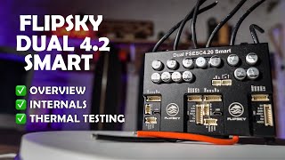
Flipsky 4 2 Smart ESC Reviewed - 50A continuous Smart ESC (+ GIVEAWAY!)
4K views · 2021-11-08 19:00:12
FLIPSKY FS-SW1 Battery Lithium-Ion Spot Welder Review
11K views · 2020-12-14 19:00:01